I built a robot which uses an iPod as its brain and the questions of how to interface the iOS device to the hardware was probably the most difficult early decision in the design process. There appeared to be four options:
This blog post has an accompanying video which briefly shows the robot that I mentioned above in action, and also demonstrates using the technology this blog post covers:
Since I wanted absolute isolation of the iOS device and the hardware I was creating, I considered using an optoisolator and running the audio output through an LC filter to trigger the optoisolator from the audio output. It seemed a lot simpler to just treat a portions of the screen of the iOS device as the LED side of the optoisolator and it was also cheap and really easy. To get information to the analog port of an Arudino Pro Mini, only two parts are needed, a phototransistor and a pulldown resistor, together they cost about 20 cents.
Capabilities
The technology isn't just a curiosity, we're using it to drive a robot, so it can be used in practice. The main issue is that the transfer of information from the iOS device to the robot is relatively slow, additionally, it is one way only, from the iOS device to the hardware/Arduino. The delay in the phototransistor is minimimal, on the order of nanoseconds. The read delay on the arduino pin is a few milliseconds to stabilize, which is not the most significant delay. The most significant delay by far is the changing of the pixels on the screen of the iDevice, which can be more than 100 ms. This is significant for two reasons. If you need high performance, you probably should use OpenGL ES to update the screen. The second is that it makes more sense for each light (group of pixels that carry information) to carry information for one state, rather than using a group of lights to carry information in parallel.
How to make a demo device driven from an iOS device
This is a parts list for the demo shown in the video:
| Item Name | Number | Unit Price | Source |
| TIP 120 Transistors | 2 | $0.47 | Mouser |
| 1N4004 Diodes | 2 | $0.09 | Mouser |
| 1K Ohm Resistors | 2 | $0.07 | Mouser |
| 10K Ohm Resistors | 2 | $0.09 | Mouser |
| Phototransistors | 2 | $0.14 | Mouser |
| 1 uF Ceramic Capacitors | 2 | $0.24 | Mouser |
| Gear Motors | 2 | $5.58 | RobotShop |
| Wheels | 2 | $3.09 | RobotShop |
Rough cost, total, is around $15, assuming you have an Arduino of some sort and a breadboard. If you use LEDs rather than a motor, you can dispense with the motors, caps, diodes and TIP 120, and it will cost less than a dollar to test this out.
To assemble the test setup with the Arduino, set up your breadboard like this:
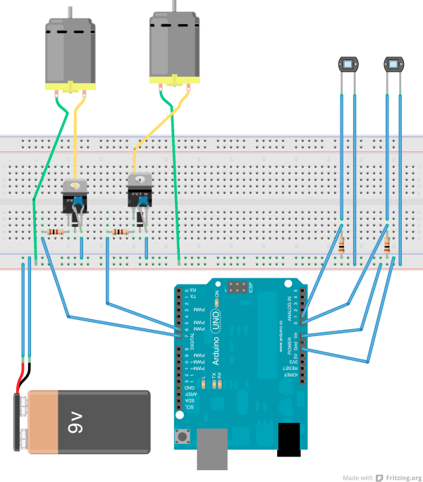
A 9V battery is used as the power source, with the Vin and ground of the Arduino supplied from the breadboard. The inputs to Analog 0 and 1 of the Duemilanove are from the phototransistor. Note that the phototransistor runs reversed biased (ie, connect the cathode, which is the shorter of the two leads, to high). The outputs from digital 6 and 7 go to the two power transistors via a 1K Ohm transistor. The diode and the capacitor are to prevent reverse emf and noise from the motors. The band on the diode should be towards the middle pin of the transistor.
iOS code
I'm including the demonstration app that I wrote here. There is nothing very complicated about it, but you need to remember to update the lights on the main thread, or they will update very slowly. The thing that most limits the performance of this technology is updating the output on the screen, but using OpenGL ES could improve that markedly. This code just uses UIKit.
Running the demo
To run the demo, you will need to have something that will hold the LEDs against the iPod screen, and then put the phototransistors into place against the screen. You will also need to load the Sketch to the Arduino. After that, you can turn the app on and move the slider back and forth and the motors should respond (see the video for a demo).
Without an Arduino
For this simple case an Arduino is unnecessary (for the more complicated case where you are operating an H Bridge, the Arduino is useful since it can ensure that you are not opening both sides of an H Bridge at once). To swap out the Arduino, add a transistor so that you have enough signal to trigger the TIP 120 power transistor.
Acknowledgements and Further reading
The motor controller part of the circuit is mostly from: http://www.instructables.com/id/Use-Arduino-with-TIP120-transistor-to-control-moto/
I'm putting together a post about creating the robot shown in the video. When it is available, I'll put a link to it here (it will be posted to this blog).
 Computer vision
Artificial intelligence
Effecting the physical world
Our robot controller app is available in the app store and will be be available soon for Android