I use transistors frequently to drive components that take more current than an Arduino pin can supply, and sometimes also to amplify signals from discrete components. This post attempts to answer two common questions about transistors:
NPN Transistors (for example, 2N3904, 2N22222, TIP 120)
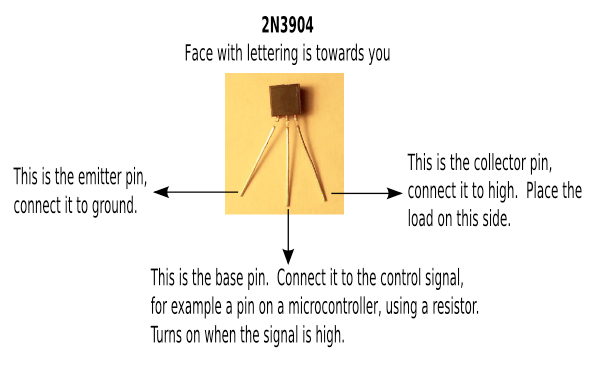
For small signal transistors, the base pin is generally the center pin, but be sure to read the data sheet for the pinout, since the TIP 120, for example, uses the left pin, as the front is facing you, as the base pin.
I use NPN Transistors very frequently along with an Arduino so that the pin on the Arduino only needs to provide a low current which can be amplified by the transistor in order to drive anything from a group of LEDs to a motor.
When you run this code on an Arduino:
PNP Transistors (for example, 2N3906, 2N2907, TIP 125)
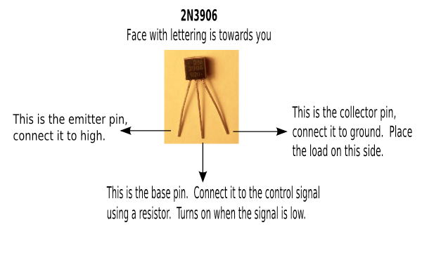
PNP transistors work similarly to NPN, but they are switched on by opening a path to ground on the base, and the load is put between the collector pin and ground. I don't use these very often, since it is easier to use an NPN with an Arduino output pin. The discussion above for NPN transistors, except for the changes noted in this paragraph, also apply to PNP transistors.
As noted above, be sure to read the data sheet for the pinout, since the TIP 125, for example, uses the left pin, as the front is facing you, as the base pin.
Calculating Base Resistor Value
I think most hobbyist, and many people who design circuits as part of their job, including me, use base resistor values from fragments of circuits that are available on the web, typically 1K Ohm. The way to calculate the correct value is:
Rb=(VPin - Vbe)/Ib
Where:
So lets say you want to drive two leds that require a combined 60 mA and you have a beta of 80, so you want a base current of around 1 mA. You also know that the digital pin provides 5 Volts and your Vbe for a 2n3904 is 0.65V, then you would calculate the value:
(5V-0.65V)/0.001A=4.35KOhm
However, you would probably be just fine using a 1K Ohm resistor, since most sources say you generally want to overdrive the transistor. I think that is may be more important to make sure that you use a small enough value that you will completely saturate the transistor, while providing a high enough resistance to protect it.
Two sources for more information about how to calculate the base resistor value are here (from an instructables question) and a calculator here.
 Computer vision
Artificial intelligence
Effecting the physical world
Our robot controller app is available in the app store and will be be available soon for Android